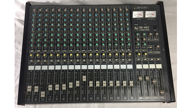
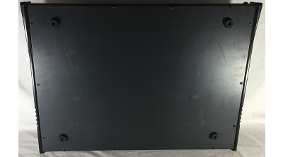
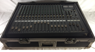
Electro Voice 16-Channel Pro Stereo Mixer
$585.00
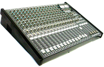
Model# BK-1642
Old School 16-Channel in and 4-Channel out EV BK Series Pro Stereo Mixing Console
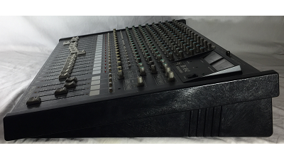
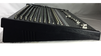
I am very pleased to offer this Electro Voice 16-Channel Pro Stereo Mixer in really good cosmetic condition and excellent working condition. 16 In and two subs one main and one monitor out including onboard Phantom Power all works like new very clean and clear. This Pro Stereo Mixer Console powers on and all indicator lights are functioning, all controls knobs and sliders adjust with ease and the gauges are in excellent condition.
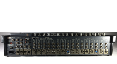
This vintage mixer is perfect for a band, church or school that need a nice clean mixer. It is fully functional 16 channel analog mixer with a very compact footprint. May show a few slight marks or scratches but everything is fully functional and in overall great condition from the use of its custom case. Features include 16 complete channels with XLR, ¼” and insert inputs on each channel, pfl metering, 2 subgroups, monitor and 2 aux, tape I/O, etc.
The Electro-Voice BK Series was designed to deliver exceptional performance and provides the flexibility and sonic quality required by any working musician. The five mixing buses and channel patch points enable the use of multiple effects and processors. The pre-fade listen or solo system is invaluable for fine-tuning the mix. Vocalist will find the reverb to monitor send useful in providing a "dry mix" for stage monitors. With the addition of on-board phantom power, any dynamic or condenser microphone can be used without separate power supplies.
The input channel is the beginning of the signal processing phase of the mixer. Each input channel will accept one signal source which may be then equalized, have reverb or other effects added, sent to a monitor system, and last but not least, sent to the main system for the audience to hear. Each input has a low impedance microphone input (the 3-pin XLR or Cannon connector) and a high impedance mic or line input (1/4 in. phone jack). The line input will accept signals from an instrument, high-impedance microphone, tape machine, electronic drummer or almost any other audio source. Always make sure that the channel fader (sec. 1 H) or master faders (sec. 2H) are down before plugging or unplugging input sources.
The TRIM control adjusts the gain or amplification of the input amplifier. This is necessary to accommodate the wide variation in signal strength presented to the mixer by the almost endless variety of signal sources — vocal mics, instrument mics, tape machines, etc. The TRIM control allows you to optimize the amplification for each individual input source. This results in the best signal-to-noise ratio ( . . . no hiss) and at the same time, best freedom from overload distortion.
The TRIM control is used to match the gain of the first preamp stage to the signal strength of the source being run through the channel. To get the cleanest, quietist operation from the board it is important that the TRIM control be properly set.
To set up a mix, first set all TRIM controls at "0" (minimum). Set all the input and subgroup slide faders at "0". Then adjust the TRIM controls for a rough mix (see sec. 11), and do the fine tuning with EQ and faders as necessary. Whenever possible, it is best to try to maintain that "straight line" relationship between all faders. When this is done, all the levels within the console are very close to being optimized for the best noise and distortion performance. Once the correct TRIM setting is established, make all volume adjustments with the appropriate channel fader (sec. 1 H).
In general, the lowest noise operation (greatest dynamic range) will be obtained when the TRIM control is set at a point just below where the CLIP light would flash when set to their designated normal operating points, the circuits in the board are optimized for minimum noise and distortion. In other words, the signal levels are high enough to keep noise from creeping in and low enough to ensure plenty of headroom and freedom from clipping distortion. If the fader must run wide open to get enough level, turn up the TRIM control or increase the setting of the left and right sub-master controls. Conversely, if the fader must be pulled way back to get the right level, the TRIM control or stereo sub-masters should be adjusted. Adjust the TRIM control if the CLIP LED lights, otherwise adjust the stereo sub-masters. For optimum performance, the channel FADERS (sec. 1H) should be run close to the "0" mark.
The channel patching jack can be used with equalizers, limiters, compressors, external reverb or delay systems and the like. Just be sure the device you want to patch in has line level unbalanced inputs and outputs. The signal at the insert jack can drive loads of 2,000 ohms or greater, and the external processing device should have a low out- put internal impedance (100 ohms or less).
BK-16-Channel Stereo Mixer Features:Includes:
1 B. EQ CONTROLS 1.D. MONITOR SEND
Equalization can be more simply described as The monitor send control sets the level of that input
sophisticated tone control. The EQ circuits used in signal in the monitor mix. It is independent of all
the BK-1632 have a substantial amount of boost input channel controls except TRIM control (sec.
and cut capability. 1A). It is not affected by the channel EQ controls
or slide fader. Thus, it is independent of, and not
This wide range can be a bonus when dealing with affected by, changes in the main or house mix.
instrument signals, poor acoustics or other
problems. Use them sparingly, however, for the 1E. AUXILIARY SEND
best results.
The auxiliary send control sets the level of that input
signal in the auxiliary mix and is switchable PRE-
1. HIGH EQ 10 kHz SHELVING TYPE POST-EQ and fader. In the PRE position it serves
±15 dB as another "MONITOR OUT" and in the POST
Controls the treble content of the input signal. position, another "EFFECTS OUT."
Turning the control counterclockwise decreases The auxiliary send may also be used as a send for
the amount of treble, clockwise increases it. recording
2. MID EQ 3 kHz PEAK/DIP
±12 dB 1F. PAN POT
Controls the midrange content of the input Short for "panoramic potentiometer." This control
signal. Turning the control counterclockwise allows you to place the channel's input signal within
decreases the amount of midrange, the stereo image by assiging more or less of the
clockwise increases it. signal to the left or right submaster controls.
Turning the panpot to the left of center moves the
3. LOW EQ 100 Hz SHELVING TYPE apparent source toward the left channel, turning it
±15 dB to the right moves the source toward the right chan-
nel. Centering the control makes the apparent
Controls the bass content of the input signal. source centered between the channels. If all inputs
Turning the control counterclockwise decreases are panned center, the result is mono. Proper use
the amount of bass, clockwise increases it. of the PAN control cna sometimes help to control
acoustic feedback in a sound reinforcement system
1C. EFFECTS/REVERB SEND by "panning" a mic away to the loudspeaker on
the opposite side of the stage.
The EFFECTS/REVERB send control determines
how much of that input signal is sent to the internal
spring reverb and/or external effects. It is affected 1G. PFL
by the channel EQ controls (sec. 1 B) and the PFL (Pre-Fader Listen) allows the operator to
channel fader (sec. 1 H). monitor any pre-fader siganl individually or in com-
Turning the control clockwise increases the amount binations, through the headphone output.
of reverb and/or effects applied to that input signal; To activate the PFL simply depress the appropriate
counterclockwise decreases the amount. switches. The status indicator will light indicating the
Since each channel has its own EFFECTS/REVERB pre-fader signals being monitored.
send, some channels can have reverb or effects In the normal position (all PFL switches off) the
and others none. Note that since the internal reverb headphone circuit monitors the output of the "Left"
and external effects share a common send, they and "Right" Submaster outputs.
will always have the same sources. That is, it is not
possible to have only reverb on one input source The audio level oat the HEADPHONE jack (2 R) is
and only effects on another input source at the controlled by the PHONE GAIN control (2 Q).
same time (unless the insert point is used). It is
possible to have reverb and effects simultaneous-
ly on both input channels, however. 1H. CHANNEL FADER
The EFX/REVERB send may also be used as mono The side fader controls the output level of the chan-
send. This might be useful for a tape recorder send, nel as it is fed to the subgroups. The control should
for instance. be normally set at the "0" mark. With all controls
Finish ~ Grey
Year ~ 1985
Made In ~ United States
IEC AC Power Cord
Owners Manual
See the custom made ATA case here ➫ Tour Case
Used – Very Good
Same Day Shipping - Ships from Blonds personal stash
Located in: New Orleans, Louisiana, United States
Handling Cost:
$20.00 will be added on items over 30lb
$50.00 will be added on items over 100lb
Free local pickup
Shipping: Calculate
make an offer
